Digital Electronics and Logic Gates
The switching action of a transistor makes it especially suitable for use in digital logic circuits where the output is either 0 or 1 depending on the input. Applications of such circuits are to:
All these things and indeed many more can be done with ELECTRONIC LOGIC CIRCUITS. These circuits are ones that can make decisions. Different decisions need different circuits.
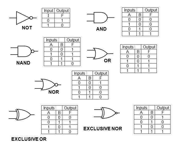
If you refer to the switching circuit for the transistor you will see that the output voltage is high (consider this as 1) when the input voltage is low (consider this as 0).
This is the basic NOT gate - there is an output when there is not an input.
Combinations of these switching circuits can be made into logic gates that will perform simple decisions within a microprocessor. These logic gates are the basis of all decisions within computers and from now on we will consider their effects rather then their internal structure.
We will consider the following types of logic gate:
(a) NOT gate - this gives an output 1 for an input of 0
(b) NOR gate - this gives an output 1 for neither of two inputs 1
(c) OR gate - this gives an output 1 for either of two inputs 1 and both inputs 1
(d) AND gate - this gives an output 1 for both two inputs 1
(e) NAND gate - this gives an output I for either but not both of two inputs 1 or both inputs 0
(f) EXCLUSIVE-OR - this gives an output I for either but not both of two inputs 1
(g) EXCLUSIVE-NOR - this gives an output 1 when both inputs are 0 or 1

